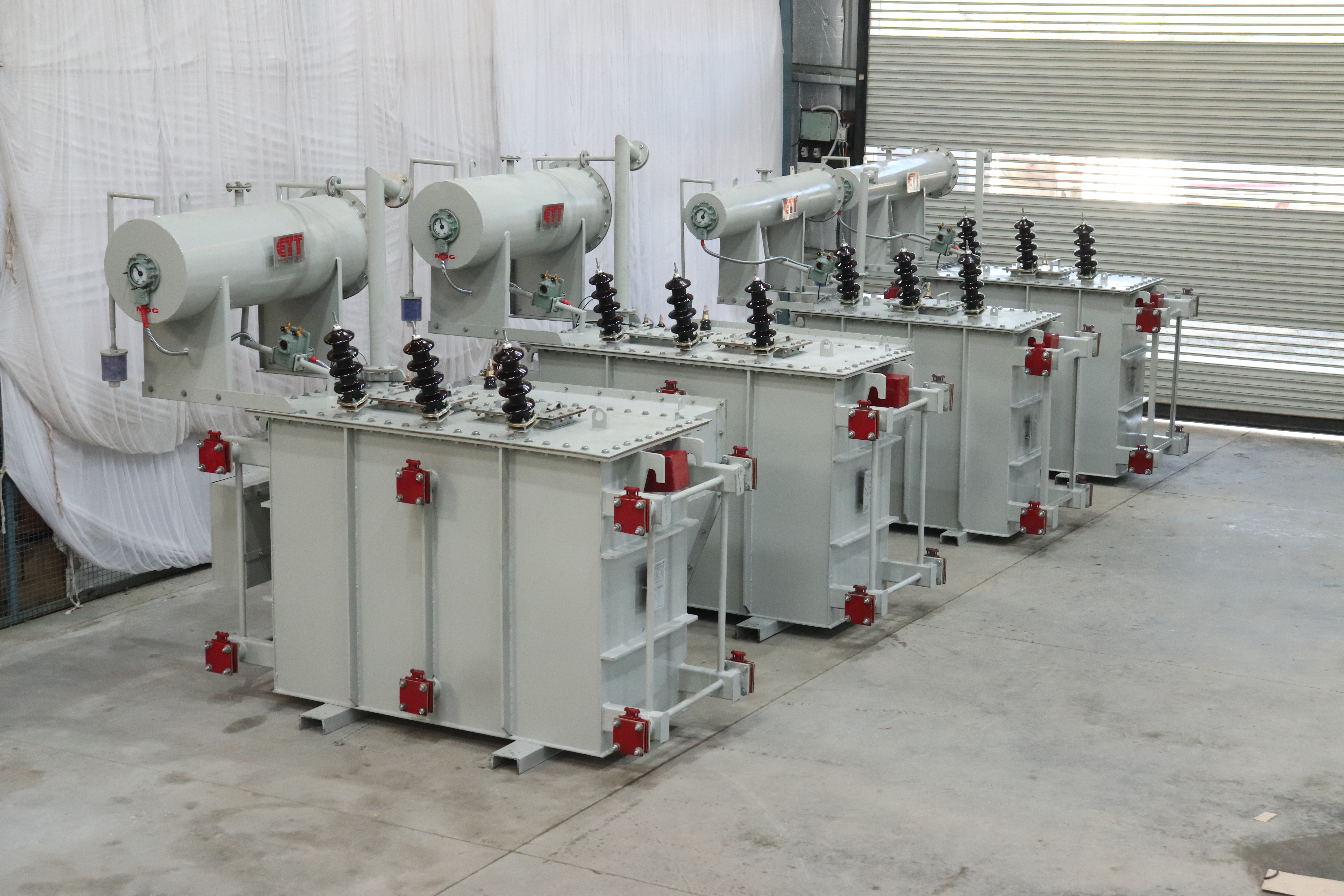
Furnace Transformer

Ferrous and non-ferrous metals require induction melting and induction heating and the Furnace Transformer is designed to serve that purpose. The design of the Furnace Transformer connects it with the inverter circuit to apply a medium frequency (in general 500 or 1000 Hz) voltage to the induction coil. The induction coil produces the magnetic field to induce eddy currents in the charge to heat it. However, the rate of heat generation can be enhanced with medium frequency. Here is a brief outline –

  • Induction Furnace coil is made of heavy copper tubing
  • Pad-mounted Transformers - both in and outdoor
  • Multi-paper covered copper conductor
  • Managing IS-2026 and IEC 60076 application standards
    1.  

Features Of Furnace Transformer:-

  • Primary and Secondary side windings have in between electrostatic earth shield to protect the rectifier elements against voltage surges in primary side windings
  • Limitation of harmonic current losses by using reduced current densities
  • Limitation of core losses from harmonic flux by using reduced flux density
  • Transformer is designed to manage the 6 Pulse/12 Pulse or other rectifier circuits requirements by the furnace manufacturer
  • Conforming to IS 2026 and IS 4540 – specifications for power transformer and rectifiers

Technical Specifications:-

Type

Indoor/ Outdoor

Duty

On-Load / Off Load

Voltage Class

3.3, 6.6, 11, 22, 33 KV.

Vector Group

Dyn11 or other specified by customer

No. of phase

3 phases

Frequency

50/60 Hz

Tap Range

±10% in on load and ±7.5% in off load or other specified by customer.

Winding Material

Copper with multiple paper covering

Applicable Standards

IS-2026, IEC 60076

Painting

Epoxy or specified by customer

_ask_anytime_

Frequently Asked Questions

whatsapp Icon